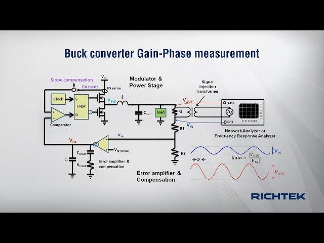
How to measure Buck converter loop gain and phase
Комментарии:

Amazing knowledge!
Ответить
墙裂建议增加中文字幕
Ответить
Yo this video is the bee's knees... Reealy really so great
Ответить
It is briliant tutorial like previous about fast prototyping! Thank you master :) for linking theory with practice. This video puths TI's simmilar one on the knees. Great job!
Ответить
Is this type III compensator?
Ответить
can you explain why the insulating cap improves the noise problem?
Ответить
Brilliant Lecture of FRA of Buck Converter. Seems this is the type 2 compensator.
Ответить
Thank you so much for the useful video. Could you make another tutorial video to show how to measure non-opto Flyback converter loop gain and phase ?
Ответить
Great job! Thanks for sharing knowledge!
Ответить
Instead of a magnetic transformer (balun) to inject the signal, caný a differential output amplifier (LMH5401IRMST) be used? Does it make sense to use a kind of calibration (modifying the software) to compensate transformer losses by modifying the generator amplitude?
Ответить
Very helpful! Thanks! From China.
Ответить
Great Video! Thank you for sharing!
Ответить
Roland, that was a great video!
Ответить
Why can’t we just break the loop and measure the loop gain and phase that way??
Ответить
As a 30 year designer, this video demonstrstes the very good experience of the presenter.
Ответить
Incredible video. Thank you so much!
Ответить
Crystal clear explanation.. gives clarity to the viewers. Great job sir.
Ответить
It’s a very fabulous video
Ответить
Hi Richtek,
I would like to obtain an open-loop bode plot of a boost converter. But, I don't know where to place the injection transformer and measurement points for the scope. Can you please help me with that?
Greetings & Thanks

Hello, Genius, I'm getting a big doubt about LCD/LED TV's COF IC. I'm not getting any idea about this, because, I don't have a Microscope or DSO. If you are interested to help, please take a small test about this COF with IC & without IC.
Everybody knows all signals coming from the T-CON board to the LCD panel with the help of the COF bonding method and its signal testing points also given in this COF.
But, why need this COF and what is the role of this IC? This IC's data is hidden or this is not an IC. Please clarify the truth about this COF.🤔

Very informative video ! I have a question could we place the injection resistor with the transformer also inside the voltage divider in case we want to measure very high voltages ? On TOP it´s very hard to protect the measurement equipment from high voltages. I would also place the oscilloscope probe within the voltage divider If that´s possible.
Ответить
This video is useful. Thank you very much!
Ответить
Great explanation and no need for multi thousand dollars equipment! Thank you sir!
Ответить
Hi,
I have a buck converter based on IC# lm25116
how to connect an indicator led light or buzzer to the ic to know it is in the hiccup mode .

Drawn like this (on the preview) it looks like a typical D-class amplifier. And I think all the best technics of making a modulator (purifi, ncore, ice) will work perfectly in case of a buck converter as well
Ответить
Thank you. This has been the most easy to comprehend explanations of gain/phase response, and it's measurement, for a buck converter.
Ответить
Thank you for this very informative video! Do you think the 8 bit picoscopes will give usable results?
Ответить


![[유진 커플 1화] 결혼은 포기했던 제가 이렇게 사랑하는 사람을 만나게 됐습니다 #국제결혼 #국제부부 #국제연애 #국제커플 #베트남국제결혼 [유진 커플 1화] 결혼은 포기했던 제가 이렇게 사랑하는 사람을 만나게 됐습니다 #국제결혼 #국제부부 #국제연애 #국제커플 #베트남국제결혼](https://rtube.cc/img/upload/OGFrRW1idjkyVXE.jpg)


