Комментарии:

Jan, you are the master of tinkering!
Ответить
when you are going to mount this permanently, it is best to solder the wires directly and not use screw terminals. screw terminal of this type you use I do not like. soldering is safer over time and gives the best result !!!!
Ответить
would never use double-sided tape, easy to loosen.
I would have used (M3 Hex Nut Spacing Screw Brass) search for it on the internet

Does it have enough power fora C64 using a 1750 Memory Expansion Unit?
Ответить
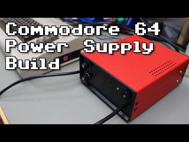
An awesome project! I am not sure where I've been but I haven't seen (or remember) this PSU design -- very cool. And that red enclosure is fantastic! Coincidentally, I purchased the same model, but in black, from Banggood sometime last year. Great work, again -- really enjoyed, as usual.
Ответить
Why does no one have both power leads only coming out of the back so it will be neater and more conveient on your desk it;s the biggist grip all retro computer owners have.
Ответить
nice project!!
Ответить
Hot snot :D
Ответить
Just color both ends of the green and yellow ground wire with a colored sharpie or similar, bingo! not green any more!
Ответить
I was just looking at the schematic you supplied and noticed that the L1 is basically bypassed with a solid connection, it’s shorted out?
Ответить
Great build. One upgrade I might do is to put a voltage monitor on the front of the case. The case you used would be perfect for it.
Ответить
Very nice power supply. Great video as well.
Ответить
Good game at the end :)
Ответить
Just put a shrink tube over the yellow/green wire so it doesn't suggest it's PE anymore.
Ответить
Another PSU option is to “re-brick” a non-epoxy original. I did a video 😁
Ответить
Great video, as usual. Keep them coming.
Not quite to code though and potentially dangerous. The Earth wire yellow/green must be the longest wire! You made it very short. The reason for this code is in case the mains cable is pulled out by force, the ground remains connected until the end. Right now, because its so short it would be ripped out first and you lose all grounding while the mains might touch the case.
But you built it like a tank, no need to worry.

There are no losses in the cable when there is no load connected (Ohm's law - U = I * R. No current - I = 0 - no voltage drop).
Ответить
Video leider auf Englisch.
Ответить
Can I use a small pot instead of the resistor (390) for adjusting the overvoltage cutout?
Ответить
I would recommend sandwiching those earthing ring crimps between 2 external shake proof washers for better earth bonding.
Ответить
The question is: How much did you pay for all of the parts?
Ответить
Good video, though I was a little disappointed. I was hoping you would go into more details about why the original power bricks fail, and what that does to that machine, including opening up both to point to the relevant components. I guess the history of power brick failures would be for another video.
Ответить
So a C64 will not work with a modern 5V power brick with a switched psu inside?! If so why? I don't like transformers anymore...
Ответить
Nice Video!!
My Question: Is the PSU strong enouth for the C128 too?

When using single transformer where secondaries are used for both 5V DC rail and 9V AC rail there is no galavanic isolation between the rails like there is in original C= power supply. Though this doesn't really matter as the 9V rail inside the C64 after it's rectified uses 5V DC rail's ground.
According to measurements in the PDF this has 40-50mV ripple noise that is fairly high for a linear power supply. Certainly C64 will work with that but the filtering isn't very effective. Adding some RC-filtering between rectifier and the regulator will get the ripple to 10mV range.
I would probably add 1-5 ohm resistors parallel to C1, C2 and C3 and bump the values of C2 and C3 to 2200uF because why not.

Some experiences over the years with DIY power supplies ...
Building a strain relief (Zugentlastung) that lasts isn't an easy thing. Turning the cable, throwing the device from the table and so on. Easiest way is to use an IEC connector (Kaltgerätestecker), but it's a bit more work to get a rectangle hole for it. If you go the route of a fixed cable, make sure that the PE is longer than the other two and therefore is the last one to be ripped off when the strain relief fails.
The "Klebepads" don't last on devices that get's warm (at least good quality ones 25+ years ago didn't), I'm using screws.
Putting cables directly into the screw terminals will not last if you need to disassemble the power supply a few times. Soldering is a bit better but won't work good as well. I'm using wire end ferrules (Aderendhülsen) with a plastic collar, that's even good for "flying prototyping".
Using labels from a label printer will remember yourself after a few years what this thing is for, "C64 Power Supply", "200mA T", "green=ok", ...
Don't ask me how I learned all of the above ...

Hi Jan, can You tell me where can i buy a joystick like the one you have? Thanks. Hi Antonio
Ответить
Hi Jan. Can you point me to the gerber files for 9VAC to 5VDC board (with over volt protection) with no on-board transfomer featured in the first part of this video? I've looked through the links in the video description and can't see it.
Ответить
FWIW in Australia under AS3000 you can use the PE conductor for whatever you want so long as you sheath the visible parts so it doesn't LOOK like PE ;)
Ответить
Aaah! That board - it's not through-hole-plated prototyping board like the kind I accidentally ordered and wondered why it was expensive. You can remove the pads from your board just by scorching them with the soldering iron!
Ответить
Anyone building 1 or 2 of these i can buy? im from denmark and will pay shipping and the cost for creating it.
Ответить
Gran video Jan,alimentatore stupendo,sei il numero uno.ciao.
Ответить
Excellent video Jan! Could you or anyone else in the comments sum up what would be needed to make this a multi-output PS for maybe a disk drive or two? Thanks!
Ответить
I think I would have preferred pots than fixed resistors in that design. But it looks nice.
Ответить
how do you go from the c64 video output to a new display ?
Ответить
I can’t believe I just watched someone build a custom power brick lmao
Ответить
Very nice job!
Ответить
The number LM2576T-ADJ seems familier. I THINK I've used one of those before, along with a specific version for 5 volts.
If it is the one I'm thinking of, it's a 5 pin device, and it needs a diode and inductor on it, along with a big fat capacitor.

have u seen a BBC micro emulator for the Atari st? thanks....
Ответить
Firstly, I'm not that enamored by the PCB rectifier board. Really that circuit should have multi-turn potentiometers to set both the main voltage and overprotection voltage. I know that a lot of us here in the UK will stick a ring (say, 5mm) of red, black, or blue piece of heat-shrink on a misused Earth (PE) wire just as an indicator. Speaking of Earth wires, they really should be the longest of the three live inputs and secured with a star washer. Also, I'd personally like to have more clearance between the bottom of the boards and the metal case and/or some insulator.
The heat-shrink around the DIN plug pins is bloody genius! Thanks for that idea!
Your videos are great, Jan. Please keep 'em coming!

Great video, Jan👍🏻! I stumbled over it while doing a power cable for my C64 and saw your „trick“ with the pinheaders. Nice one, think I‘m gonna use this method too. Where are they from respectively what is their parts number?
Ответить
I can't find the exact transformer you using. Can you please provide me a link? :)
Ответить


